 LANGUAGE
 English
 Deutsch
 Español
 Français


What is the Best Hydraulic Pump for Your Log Splitter? Selection and Troubleshooting Guide
Understanding the Role of a Hydraulic Pump for Log Splitter Systems
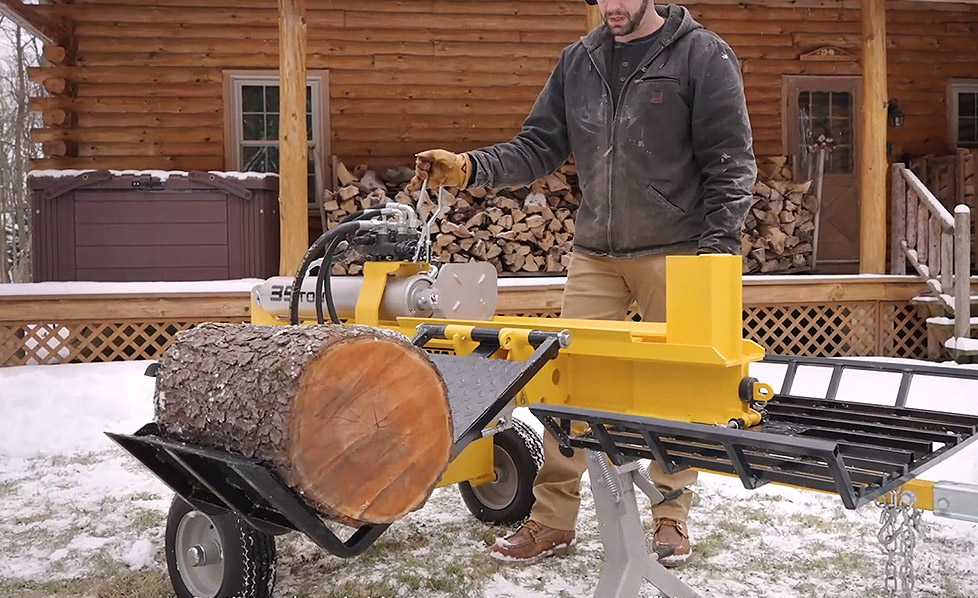
A log splitter relies completely on fluid power to convert mechanical energy from an engine or motor into force. At the heart of this system sits the hydraulic pump for log splitter applications, which dictates how fast the ram moves and how much force it can exert on a piece of hardwood. Selecting the correct pump determines whether a machine stalls under load or efficiently powers through knotty wood logs.
In standard industrial machinery, single-stage pumps supply a constant volume of oil regardless of the pressure. However, for a logsplitter pump, this setup is highly inefficient. Splitting wood requires two distinct operational phases: a high-speed approach phase where the wedge moves quickly toward the wood, and a high-force splitting phase where the wedge forces its way through tough grains. Achieving both phases with a single-stage pump requires massive engines that are not cost-effective for portable machinery.
This reality makes the dual-stage hydraulic pump the industry standard. By utilizing two distinct internal gear sets, these components automatically shift profiles based on system pressure, providing high volume when resistance is low and high pressure when resistance increases. Understanding this mechanical transition is essential for any technician executing a log splitter pump replacement or custom build project.
How a 2 Stage Log Splitter Pump Operates
The internal mechanics of a 2 stage log splitter pump consist of two separate gear pumps housed within a single body, sharing a common drive shaft and inlet port. These are designated as the high-flow (low pressure) gear set and the low-flow (high pressure) gear set. An internal differential unloading valve continuously monitors the system pressure at the outlet port to determine how fluid routes through the circuit.
During the rapid advance phase, system pressure remains below a preset threshold, typically around 500 PSI to 900 PSI. The internal unloading valve remains closed, forcing the output of both gear sets to combine and flow out to the control valve. This action supplies maximum fluid volume, allowing the cylinder rod to extend rapidly toward the wood log.
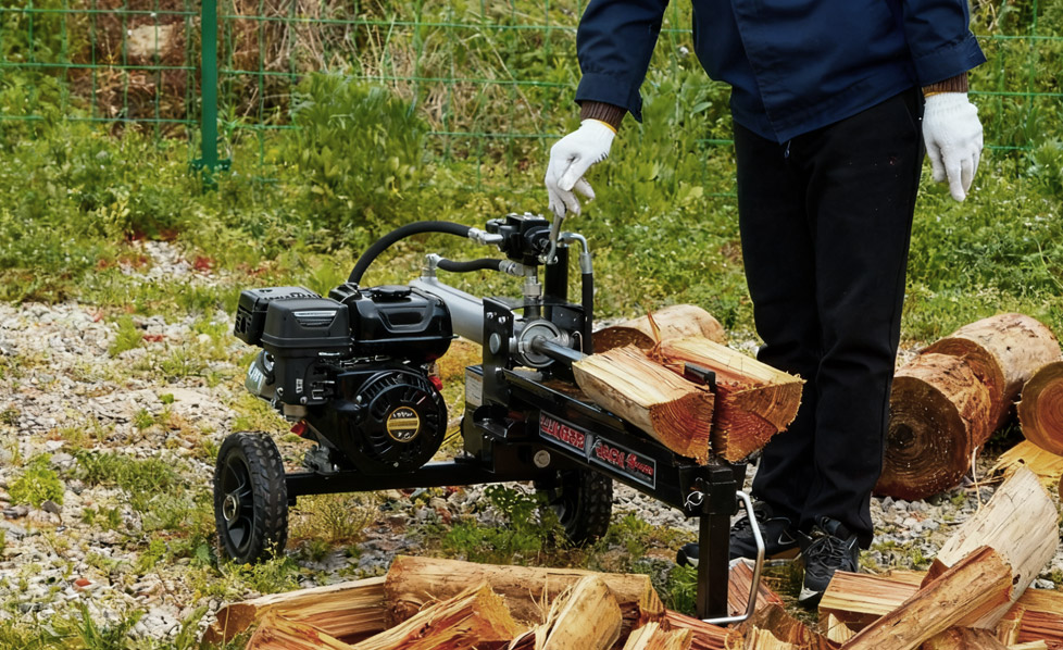
When the wedge meets resistance from a log, the system pressure rises sharply. Once it crosses the unloading valve setting, the valve shifts internally. This bypasses the discharge of the large high-flow gear back to the suction side of the pump at minimal pressure. Meanwhile, the small low-flow gear continues to pump fluid into the high-pressure line. This drops the volume output but focuses the engine horsepower exclusively on creating high pressure, up to 3000 PSI or more, allowing the system to split tough wood without stalling the drive engine.
Selecting Capacity: 16 GPM vs 28 GPM Log Splitter Pump Systems
Choosing between different flow ratings involves calculating the matching capabilities of your engine, pump, and hydraulic cylinder. The most common sizes found in commercial and heavy DIY builds are the 16 gpm log splitter pump and the 28 gpm log splitter pump. These nominal flow rates represent the total combined flow of both internal stages operating at high speed under low resistance.
A 16 GPM model typically requires a gas engine rated between 8 and 9 horsepower to maintain performance when shifting into the high-pressure stage. This configuration balances cycle times with modest engine sizes, making it an excellent match for cylinders with boring diameters of 4 inches to 4.5 inches. On the larger end, a 28 GPM configuration requires a minimum of 13 to 15 horsepower to run effectively. It is designed for massive cylinders, usually 5 inches in diameter or greater, to deliver very fast cycle times on professional-grade machinery.
| Pump Flow Rating | Required Engine Power | Inlet Port Size | Outlet Port Size | Target Cylinder Bore |
|---|---|---|---|---|
| 11 GPM | 5 HP to 6.5 HP | 1 Inch Barb | 1/2 Inch NPT | 3.5 to 4.0 Inches |
| 16 GPM | 8 HP to 9 HP | 1 Inch Barb | 1/2 Inch NPT | 4.0 to 4.5 Inches |
| 22 GPM | 11 HP to 13 HP | 1 Inch Barb | 3/4 Inch NPT | 4.5 to 5.0 Inches |
| 28 GPM | 13 HP to 15 HP | 1-1/4 Inch Barb | 3/4 Inch NPT | 5.0 to 6.0 Inches |
Executing a precise GPM calculator for log splitter analysis requires analyzing the relationship between cylinder volume and desired cycle time. To find the correct volume, compute the cross-sectional area of the cylinder piston and multiply it by the stroke length. If the engine lacks sufficient horsepower for the chosen GPM rating, the engine will stall the moment the pump attempts to transition from the high-flow stage into the high-pressure stage.
Installation and Mechanical Alignment Requirements
When installing a new component or setting up a complete log splitter hydraulic pump kit, physical alignment is vital to prevent premature wear. Most industrial wood splitters utilize a direct-drive setup via a machined bellhousing adapter that connects the engine face directly to the pump mounting flange. This structural mount eliminates obvious visual angular errors but does not automatically guarantee perfect concentric alignment.
Connecting the shafts requires a high-quality log splitter pump coupler, which typically consists of two sintered steel or aluminum jaw halves separated by a flexible elastomeric spider element. This log splitter engine coupling system is designed to dampen vibration and accommodate microscopic levels of thermal expansion. It cannot, however, absorb severe angular misalignment or offset parallel misalignment without wearing out the internal bearing supports of your new log splitter pump.
Technical Installation Protocol: When tightening the set screws on the jaw coupling halves, ensure you leave a tiny clearance gap, typically 1/16 of an inch, between the metal jaws and the elastomer spider. This axial float prevents the engine crankshaft from transferring thrust loads directly onto the internal gears of the pump, protecting the soft aluminum wear plates inside the pump housing from scoring.
Before filling the system with fluid, verify that the suction line from the reservoir to the pump intake uses a specialized wire-reinforced suction hose. Standard hydraulic hose is built to withstand high internal pressures but can easily collapse under the strong vacuum created by a high-displacement log splitter pump, starving the internal components of oil and causing rapid cavitation destruction.
Comprehensive Hydraulic Pump Troubleshooting Guide
When operational failures happen, systematic hydraulic pump troubleshooting isolates structural failures from configuration errors before you buy unnecessary components. Problems usually show up as a sudden loss of cutting power, noisy operation, or slow cycle speeds.
Addressing the Loss of Splitting Pressure
If the cylinder moves smoothly but stops completely the moment the wedge meets resistance from a log, the problem usually stems from an out-of-adjustment or contaminated internal unloading valve. Over time, metal wear particles or debris can lodge inside the valve seat, preventing it from sealing completely. This allows high-pressure oil to escape back into the suction side instead of routing to the cylinder. Adjusting the unloading valve screw clockwise can restore the shifting threshold, though cleaning the internal spring assembly is often required if debris is present.
Eliminating Pump Cavitation and Aeration Noise
A loud, mechanical whining sound that resembles gravel churning inside the pump casing indicates fluid cavitation or aeration. Cavitation occurs when the suction line restricts flow, causing bubbles to form and collapse violently inside the gear teeth. Aeration happens when air leaks into the suction side via loose hose clamps or a worn shaft seal. Checking line restrictions and ensuring all suction connections are completely airtight will quickly resolve these sound issues.
| Observed Symptom | Probable Mechanical Cause | Corrective Action Step |
|---|---|---|
| Wedge stops under load; engine runs fine | Unloading valve set too low or stuck open | Clean valve seat or adjust shifting pressure screw |
| Engine stalls immediately when wedge hits wood | Unloading valve stuck closed; engine undersized | Inspect unloading spring; verify engine horsepower matches GPM |
| Loud mechanical whining sound; foam in reservoir | Air entering suction line or low oil level | Tighten inlet clamps; check shaft seal; top off fluid |
| Extremely slow cylinder travel in both directions | Internal gear wear or blown internal seals | Perform a volumetric efficiency test; replace pump assembly |
System Maintenance to Maximize Component Lifespan
Preserving the efficiency of a log splitter requires regular preventative maintenance. Hydraulic fluid degrades over time due to high operational temperatures and moisture absorption, losing its film strength and leaving components vulnerable to metal-on-metal friction. Change the system fluid and replace the return-line oil filter after the first 50 hours of operation on a new machine, and every 150 hours thereafter.
Keep a close eye on operational temperatures. Hydraulic systems operate best between 120 degrees Fahrenheit and 140 degrees Fahrenheit. If temperatures exceed 180 degrees Fahrenheit, the fluid viscosity drops too low, causing internal leakage to rise exponentially and accelerating seal wear across the entire log splitter hydraulic pump kit circuit.
Always clear debris from around the pump body and engine cooling fins. Accumulated wood dust and bark acts like an insulation blanket, trapping heat inside the pump casting and accelerating wear on the internal drive shaft seal.
Frequently Asked Questions Regarding Log Splitter Pumps
Q1: Why does my engine stall the moment the wedge encounters a log?
This issue happens when the internal unloading valve fails to shift into its second stage. If the valve remains stuck closed, the pump tries to maintain high flow at maximum pressure. This overloads the engine beyond its rated horsepower capacity, causing it to stall out immediately.
Q2: What viscosity of fluid should I run with a dual-stage hydraulic pump?
Most standard systems run best on ISO 32 or ISO 46 anti-wear hydraulic oil. If you plan to operate your machine in freezing winter temperatures, shifting to a thinner fluid like Automatic Transmission Fluid can help prevent cavitation during cold start-ups.
Q3: Can I spin a log splitter pump in either direction?
No. These components are direction-specific because of how their internal suction and pressure ports match up. Running one backward can instantly blow out the shaft seal and damage the internal thrust plates. Always check the rotation arrow stamped on the housing before mounting.
Q4: How can I tell if my slow cycle times are caused by the pump or the cylinder?
Isolate the issue by checking line temperatures. Run the cylinder to the end of its stroke and hold the valve open briefly while feeling the return line. If the line gets hot fast, fluid is slipping past the piston seals inside the cylinder. If temperatures stay uniform but cycle speeds remain slow across the board, the pump gears are likely worn down.
Q5: What is the purpose of the flexible spider inside the shaft coupling?
The elastomer spider dampens high-frequency vibrations between the engine and pump shafts while compensating for tiny alignment variations. This simple part prevents hard mechanical shocks from cracking the engine crankshaft or tearing up the pump bearings.
PREV:What Size and Tonnage Log Splitter Do You Need? Electric vs. Gasoline – A Complete Guide
NEXT:Why Build Your Own Hydraulic Log Splitter? A Practical Comparison vs. Buying and DIY Construction Blueprint
NEXT:Why Build Your Own Hydraulic Log Splitter? A Practical Comparison vs. Buying and DIY Construction Blueprint
Interested in cooperation or have questions?
Related products
-

-

Vertical operation position onlyHardened steel wedge24"/61cm split len...
See Details -

Vertical operation position onlyHardened steel wedge24"/61cm split len...
See Details -

DESCRIPTION Working at horizontal position onlyAuto return hydraulic c...
See Details -

●60-Volt Brushless MotorThis reliable motor is highly efficient provid...
See Details

