Understanding Hydraulic System Fundamentals
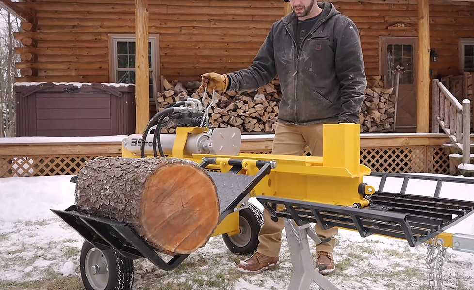
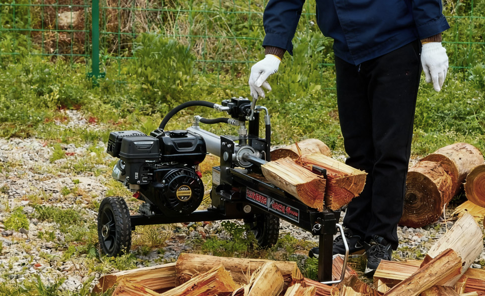
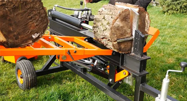
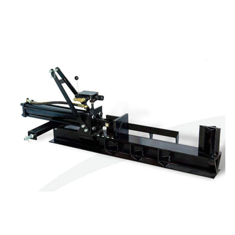
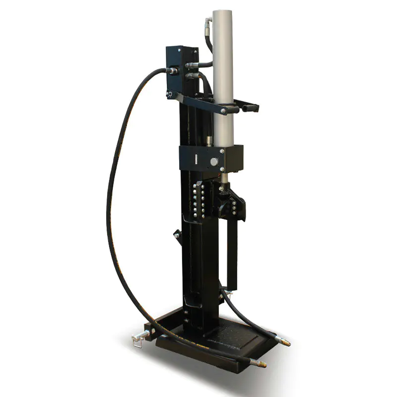
A gasoline log splitter relies on a sophisticated hydraulic system to convert engine power into splitting force. The system consists of three primary components: the hydraulic pump, fluid transmission lines, and actuator cylinders. When your splitter loses power, the root cause typically lies within one of these interconnected systems.
The hydraulic pump serves as the heart of your machine, pressurizing mineral oil to transmit force through sealed lines to the splitting cylinder. This pressurized fluid creates the mechanical advantage necessary to split dense hardwood. Understanding how these components interact helps you identify performance issues before they escalate into costly repairs.
Primary Causes of Power Loss in Log Splitters
1. Hydraulic Pump Degradation
The hydraulic pump experiences continuous stress during operation. Internal components wear under pressure, reducing the pump's displacement efficiency. A worn pump cannot maintain consistent pressure, resulting in slower splitting cycles and reduced splitting force.
Symptoms of pump failure include inconsistent splitting speed, audible grinding noises, and difficulty splitting wood that previously posed no problem. The pump typically lasts 1,000 to 2,000 operating hours depending on maintenance practices and operating conditions.
2. Fluid Pressure Loss
Hydraulic systems require precise pressure maintenance. When system pressure drops below operational thresholds, the splitting cylinder receives insufficient force. Common pressure loss scenarios include:
- Relief valve malfunction causing uncontrolled pressure release
- Pressure regulator drift from factory specifications
- Internal pump leakage bypassing pressure seals
- Fractured or loose pressure hose connections
A functional hydraulic pressure gauge provides immediate diagnosis capability. Operating pressure for most petrol wood splitter models ranges between 2,500 and 3,000 PSI during splitting operations.
3. Fluid Quality Deterioration
Hydraulic fluid degrades through oxidation, water absorption, and particulate contamination. Degraded fluid loses viscosity stability, reducing its ability to maintain pressure and lubricate system components. Over time, varnish deposits accumulate on internal surfaces, restricting fluid flow pathways.
Environmental exposure accelerates fluid degradation. Splitters stored outdoors without protective covers experience temperature fluctuations that promote condensation inside the reservoir. Neglecting fluid changes every 100-150 operating hours significantly accelerates component wear.
Systematic Diagnostic Procedures
Visual Inspection Protocol
Begin diagnosis with a comprehensive visual inspection. Look for these indicators:
| Symptom |
Likely Cause |
Severity Level |
| Oil pooling beneath splitter |
Seal or line rupture |
High |
| Slow splitting cycle with normal engine |
Pump efficiency loss |
High |
| Inconsistent splitting force |
Pressure regulation failure |
Medium |
| Discolored or dark hydraulic fluid |
Fluid degradation |
Medium |
| Oil level drop between uses |
Internal or external leakage |
Medium |
| Grinding or knocking sounds |
Internal pump damage |
High |
Pressure Testing Methods
Hydraulic pressure measurement provides definitive diagnostic data. Install an ISO-certified pressure gauge at the main pressure line near the pump outlet. Record pressure readings during different operational phases:
- Idle pressure: Should be minimal (under 200 PSI)
- Cylinder extension pressure: Typically 2,500-3,000 PSI
- Relief valve opening pressure: Usually 3,200-3,500 PSI
Pressure below specification indicates pump deterioration or internal leakage. Pressure exceeding relief valve settings suggests relief valve malfunction requiring immediate attention to prevent system damage.
Fluid Condition Analysis
Extract fluid samples directly from the reservoir using a clean, dedicated container. Observe these characteristics:
- Clarity: Healthy fluid appears transparent or light amber; opaque or dark fluid indicates oxidation and contamination
- Odor: Fresh hydraulic fluid has minimal smell; burnt or pungent odors signal thermal breakdown
- Consistency: Fluid should flow freely at ambient temperatures; sluggish flow indicates viscosity degradation
- Particulates: Any visible particles or sludge deposits warrant complete fluid replacement
Identifying and Repairing Fluid Leaks
External Leak Detection
External leaks represent the most accessible diagnostic challenges. Trace oil seepage to its source by following these steps:
- Clean all external surfaces with absorbent cloth or paper towels
- Operate the splitter through a complete splitting cycle
- Observe where new oil accumulates or seeps
- Locate the specific connection or seal where leakage originates
- Inspect hose fittings for tightness using appropriate wrenches
Loose hose connections account for approximately 40-50% of external leakage issues. Tightening fittings often restores system integrity without requiring component replacement. For persistent leaks, hose replacement becomes necessary.
Internal Leak Assessment
Internal leakage occurs when pressurized fluid bypasses seals rather than reaching the cylinder. This manifests as gradual pressure loss during operation and slow splitting cycles despite normal pump function. Common internal leak sources include:
- Worn piston rod seals in the splitting cylinder
- Damaged pump internal surfaces allowing fluid bypass
- Relief valve seat erosion permitting continuous pressure bleed
- Damaged port plate passages in the pump body
Diagnosing internal leaks requires pressure testing combined with cycle time measurement. A splitter requiring 30% longer cycle time than factory specifications likely has significant internal leakage.
Hose Replacement Procedures
Hydraulic hoses degrade through thermal cycling, ultraviolet exposure, and pressure fatigue. Preventive hose replacement every 2,000-3,000 operating hours maintains system reliability. When replacing hoses:
- Drain the hydraulic reservoir completely before disconnection
- Label each hose connection point for accurate reassembly
- Use identical hose specifications matching original equipment ratings
- Avoid sharp bends exceeding hose diameter recommendations
- Refill with quality hydraulic fluid rated for your climate conditions
Hydraulic Pump Failure and Replacement
Recognizing Pump Failure Symptoms
The hydraulic pump drives all system functionality. When pump efficiency declines, splitting performance deteriorates proportionally. Distinguishing pump failure from other issues requires systematic observation:
- Engine operates normally with no unusual sounds
- Hydraulic fluid shows no discoloration or contamination
- No external leaks appear anywhere in the system
- Pressure readings are 15-20% below specifications despite adequate fluid
- Splitting cycle times increase gradually over multiple operations
When these symptoms align, pump replacement becomes the appropriate solution. Attempting pump repair typically costs nearly as much as replacement and provides unreliable results for critical components.
Pump Selection and Compatibility
Replacement pumps must match your original equipment specifications precisely. Critical parameters include:
| Specification |
Importance |
Consequence of Mismatch |
| Displacement (cc/rev) |
Critical |
Insufficient splitting force or engine overload |
| Pressure rating (PSI) |
Critical |
Relief valve damage or system failure |
| Rotation direction |
Critical |
No pressure generation or backward flow |
| Port sizing |
Important |
Flow restriction or improper system behavior |
| SAE flange pattern |
Important |
Inability to mount pump to engine |
Installation Best Practices
Proper pump installation ensures long-term reliability and optimal performance. Follow these critical procedures:
- Verify pump rotation direction matches original specifications by checking manual diagrams
- Ensure engine shaft and pump coupling alignment within 0.1 inch runout tolerance
- Pre-fill pump case with quality hydraulic fluid before initial engine start
- Prime the system by operating engine briefly before full-pressure splitting cycles
- Monitor system pressure during initial operation, adjusting relief valve as necessary
Preventive Maintenance Strategies
Regular Maintenance Schedule
Systematic maintenance prevents power loss issues before they develop. Establish this operating schedule:
- Before each use: Visual inspection of fluid level and appearance, checking for external leaks
- Every 25 operating hours: Clean or replace engine air filter, inspect all hose connections
- Every 50 operating hours: Check hydraulic fluid temperature during operation, verify splitter pressure
- Every 100-150 operating hours: Drain and replace hydraulic fluid completely
- Every 500 operating hours: Inspect pump for unusual noises, measure system pressure carefully
- Every 1,500 operating hours: Professional inspection including pump internal condition assessment
Storage and Environmental Protection
Environmental conditions significantly impact hydraulic system longevity. Implement these protective measures:
- Store splitter indoors or under protective cover to prevent moisture intrusion
- Maintain ambient storage temperatures between 50-80 degrees Fahrenheit when possible
- Keep the reservoir cap properly sealed during non-use periods
- Drain the system completely before extended storage exceeding 30 days
- Protect hydraulic hoses from direct sunlight using opaque coverings
Fluid Selection and Management
Hydraulic fluid quality directly correlates with system performance and component lifespan. Select ISO VG 46 hydraulic fluid specifically formulated for wood splitting equipment. Premium formulations offer superior:
- Oxidation stability extending fluid service life
- Water separation capability protecting pump components
- Anti-foam properties maintaining pressure consistency
- Lubricity characteristics reducing wear on moving components
Never mix different fluid types or brands. Incompatible fluid formulations can cause chemical reactions, creating varnish deposits and reducing system efficiency.
Addressing Slow Cycle Time Issues
Cycle Time Benchmarking
Slow cycle time represents one of the most noticeable power loss symptoms. Establish baseline cycle times for your equipment by measuring splitting duration under consistent conditions. A complete cycle typically includes:
- Cylinder extension (ram moving forward): 3-6 seconds
- Wood splitting phase: 1-3 seconds depending on wood density
- Cylinder retraction (ram returning): 2-4 seconds
Total cycle times of 8-13 seconds represent normal operation. Cycles exceeding 15-20 seconds indicate performance degradation requiring investigation.
Flow Rate Reduction Diagnosis
Slow cycles result primarily from reduced hydraulic flow rather than pressure reduction. Common flow restriction sources include:
| Component |
Problem Indicator |
Remedy |
| Pump internal passages |
Flow loss despite normal pressure |
Pump replacement or professional service |
| Directional control valve |
Sluggish directional response |
Valve cleaning or replacement |
| Cylinder ports |
Asymmetric extension/retraction speed |
Cylinder rebuild or replacement |
| Fluid filter |
Gradual cycle time increase over days |
Filter element replacement |
| Contaminated fluid |
Pressure unstable, multiple symptoms |
Complete fluid and filter replacement |
Engine Performance Verification
Before attributing slow cycles to hydraulic issues, verify engine performance. A weak engine cannot drive the pump at intended speeds, reducing overall system flow. Check:
- Engine starts easily and idles smoothly without stalling
- Full throttle produces characteristic high-pitched engine noise
- No black smoke or unusual exhaust odors
- Fuel is fresh and properly mixed if required
- Spark plug shows normal firing characteristics
Wedge Condition and Splitting Performance
Wedge Geometry Impact on Efficiency
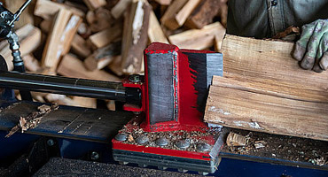
The splitting wedge transmits hydraulic force into wood fiber separation. Wedge geometry significantly influences how much force is necessary to split logs. A dull or damaged wedge requires substantially more pressure to penetrate wood fibers, increasing system strain and reducing splitting capability.
Optimal wedge design incorporates specific angles on the cutting surface. As wedges dull through use, the angle becomes less acute, requiring greater force concentration to initiate splitting. This creates an illusion of power loss when the problem is actually mechanical disadvantage.
Wedge Maintenance and Sharpening
Regular wedge maintenance directly improves splitting performance and reduces engine strain. Inspect your wedge for these wear indicators:
- Rounded cutting edges that no longer bite into wood cleanly
- Surface scratches and pitting from metal-to-stone contact
- Visible chips or cracks along the cutting surface
- Difficulty initiating splits in wood previously split easily
Sharpening techniques vary by wedge type and material. For hardened steel wedges, professional grinding maintains proper angles and material hardness. For cast iron wedges, hand filing provides adequate maintenance.
Sharpening Procedures
Proper wedge sharpening restores splitting efficiency without requiring system modifications:
- Secure wedge in padded vise to prevent movement during sharpening
- Use medium-grit grinding stone or file appropriate for wedge material
- Maintain original wedge angles by matching existing geometry
- Create uniform cutting surface with equal pressure on both wedge sides
- Remove all sharp burrs and irregular surfaces with fine-grit finishing
- Clean wedge completely and apply protective coating before storage
Sharp wedges reduce splitting time by 20-30% compared to dull wedges, creating the impression of increased hydraulic power. This represents one of the most cost-effective performance improvements available.
Seasonal Considerations and Temperature Effects
Cold Weather Performance Challenges
Hydraulic fluid viscosity increases dramatically in cold temperatures, reducing flow rates and system responsiveness. Operating temperatures below freezing require specific fluid formulations designed for cold climates. Symptoms of inadequate cold-weather fluid include:
- Difficulty starting or operating equipment in morning hours
- Sluggish cylinder extension and retraction initially improving as system warms
- Pump cavitation sounds during cold start periods
- Inconsistent pressure readings during warm-up phases
Cold weather splitters should use synthetic hydraulic fluid rated for temperatures 20-30 degrees Fahrenheit below your region's winter lows. This ensures adequate viscosity maintenance across seasonal temperature ranges.
High Temperature Fluid Degradation
Excessive operating temperatures accelerate hydraulic fluid oxidation and component wear. Monitor fluid temperature during operation, targeting 120-150 degrees Fahrenheit. Temperatures exceeding 180 degrees Fahrenheit cause rapid fluid degradation and can trigger relief valve settings inappropriately.
Overheating typically results from continuous operation without adequate cooling intervals. Implement 5-10 minute rest periods every 30-45 minutes of continuous operation to allow system cooling. This simple practice extends fluid life and maintains consistent performance.
Seasonal Maintenance Adjustments
Seasonal changes require adjustments to maintenance intervals and procedures:
- Spring: Drain winter storage oil and replace with season-appropriate fluid; inspect hoses for winter damage
- Summer: Monitor fluid temperatures closely; increase air filter cleaning frequency for high-dust environments
- Fall: Prepare equipment for seasonal use increase; upgrade to cold-weather fluid formulation
- Winter: Reduce operation intervals if equipment doesn't start easily; consider complete system drain for extended storage
System Restoration Procedures
Complete System Flush
When contamination compromises system performance, complete fluid replacement restores functionality. This procedure differs from simple fluid changes and requires systematic approach:
- Warm the hydraulic system for 10-15 minutes to reduce fluid viscosity
- Position collection containers beneath drain plugs on reservoir and pump
- Open all drain plugs, allowing complete fluid evacuation
- Install fresh drain plugs and close system components
- Reinstall or clean reservoir filter element
- Fill reservoir with clean hydraulic fluid matching equipment specifications
- Bleed air from system by operating at low throttle without cutting wood
Air Bleeding from Hydraulic Systems
Air trapped in hydraulic lines creates compressible pockets that reduce system response and efficiency. After fluid changes or major repair work, systematic air removal becomes essential. Air appears in the system through:
- Disconnected hose connections during maintenance
- Low fluid levels in the reservoir
- Cavitation within the pump due to inadequate intake pressure
- Worn pump seals allowing air intrusion
Bleed air by operating the splitter at low engine speed without engaging the splitting mechanism. Gradually advance throttle as the system responds. Air eventually exits through the pump displacement, and system response improves noticeably.
Pressure Adjustment and Calibration
After system restoration, verify pressure settings match equipment specifications. Relief valve adjustment varies between equipment models but generally involves:
- Locate adjustable relief valve on pump outlet or manifold block
- Connect calibrated pressure gauge to system test port
- Operate engine at full throttle without engaging splitting mechanism
- Measure pressure reading and compare to specifications
- Adjust relief valve screw counterclockwise to increase pressure, clockwise to decrease
- Recheck pressure after adjustment and document final setting
Frequently Asked Questions
Q1: How often should I replace the hydraulic fluid in my log splitter?
Hydraulic fluid requires replacement every 100-150 operating hours or annually, whichever comes first. More frequent changes improve system longevity and performance consistency. Environmental conditions affect fluid degradation rates; machines operating in dusty or humid environments benefit from more frequent fluid changes. Inspect fluid color and clarity monthly; if it appears dark or opaque, change it immediately regardless of operating hours.
Q2: What is normal operating pressure for a hydraulic log splitter?
Most gasoline-powered splitters operate between 2,500 and 3,000 PSI during active splitting. Relief valves typically open at 3,200 to 3,500 PSI to prevent system damage. Your equipment documentation specifies exact pressure specifications; verify readings match your model requirements. Pressure significantly below specifications indicates pump wear or internal leakage.
Q3: Can a slow log splitter be fixed without replacing the pump?
Yes, slow cycles often result from issues other than pump failure. Inspect fluid condition, check pressure readings, verify all hose connections are tight, and measure actual cycle times compared to specifications. Fluid contamination, low pressure settings, and clogged filters commonly cause performance reduction without requiring pump replacement. However, if pressure testing confirms pump displacement loss, replacement becomes necessary.
Q4: Why does my log splitter lose power in cold weather?
Hydraulic fluid viscosity increases dramatically in cold temperatures, reducing flow rates and system response speed. Cold-weather fluid formulations maintain adequate viscosity at lower temperatures. If your splitter was filled with standard fluid, switching to cold-weather hydraulic fluid resolves most winter performance issues. Additionally, allow extra warm-up time before heavy use during cold months.
Q5: Is it safe to repair hydraulic systems myself?
Some repairs are appropriate for owners with mechanical experience and proper tools. Simple tasks like tightening hose connections, replacing filters, and changing fluid can be performed safely with adequate precautions. However, pump replacement, pressure valve adjustment, and internal component repair require specialized knowledge and tools. Consider professional service for complex repairs to ensure safety and prevent system damage.
Q6: What causes hydraulic fluid to discolor and darken?
Fluid discoloration results from oxidation due to heat exposure, water contamination, or extended use beyond recommended service intervals. Environmental dust and particles accelerated breakdown through chemical reactions. Dark or burnt-smelling fluid indicates thermal breakdown from excessive operating temperatures. These conditions compromise lubricating properties and increase component wear. Immediate fluid replacement restores system protection.
Q7: How can I tell if my pump is failing versus other system components?
Pump failure exhibits specific characteristics: gradual pressure loss despite adequate fluid, decreasing splitting force over time, and audible grinding or cavitation noises during operation. Pressure gauge readings confirm diagnosis; pump failure causes pressure 15-20% below specifications. Other components create different symptoms: hose leaks produce visible oil pooling, valve problems cause erratic pressure behavior, and cylinder wear creates asymmetric extension/retraction speeds.
Q8: Should I use synthetic or conventional hydraulic fluid?
Synthetic hydraulic fluids offer superior performance characteristics including enhanced oxidation stability, wider temperature operating ranges, and extended service intervals. For wood splitter applications, synthetic fluids justify the higher cost through extended life and improved cold-weather performance. Conventional mineral oils are adequate in mild climates but require more frequent changes and exhibit reduced cold-weather performance. Choose based on your climate and operating frequency.
Conclusion: Restoring Peak Performance
Hydraulic log splitter power loss stems from identifiable sources that systematic diagnosis can pinpoint. Whether your splitter suffers from hydraulic pump failure, fluid leaks, pressure loss, or reduced flow rate, methodical troubleshooting reveals the root cause. Most performance issues involve components easily inspected with basic tools and mechanical understanding.
Implement the preventive maintenance strategies outlined in this guide to avoid power loss before it develops. Regular fluid changes, connection inspections, pressure monitoring, and seasonal adjustments extend system longevity and maintain consistent performance. When problems do occur, use the diagnostic procedures provided to identify issues accurately before investing in component replacement.
Superior splitting performance directly correlates with proper system maintenance and timely component service. By understanding how hydraulic systems function and recognizing early warning signs, you can maintain your equipment in peak operating condition and minimize downtime during critical splitting season. Consistent attention to hydraulic system health ensures your splitter provides years of reliable wood splitting capability.

 LANGUAGE
 English
 Deutsch
 Español
 Français
 русский